DMI – Graduate Course in Computer Science
Copyleft
![]() 2020 Giuseppe Scollo
2020 Giuseppe Scollo
![]()
a hardware interface connects a custom hardware module to a coprocessor bus or an on-chip bus
hardware interface design should match the flexibility of custom hardware design to the realities of the hardware/software interface
typical functions of the hardware interface:
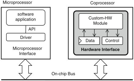
Schaumont, Figure 12.1 - The hardware interface maps a custom-hardware module to a hardware-software interface
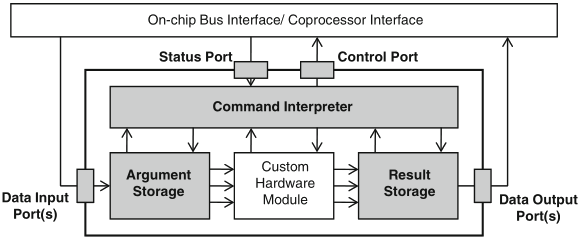
Schaumont, Figure 12.2 - Layout of a coprocessor hardware interface
components commonly found in a hardware interface:
from the perspective of the custom hardware module, it is common to partition the collection of ports into data input/output ports and control/status ports
the separation of control and data is an important design aspect, for, in a coprocessor design, the granularity of interaction between data and control is chosen by the designer
multiplexing can be implemented in different ways: the first is time-multiplexing of the hardware module ports; the second is to use an index register in the hardware interface
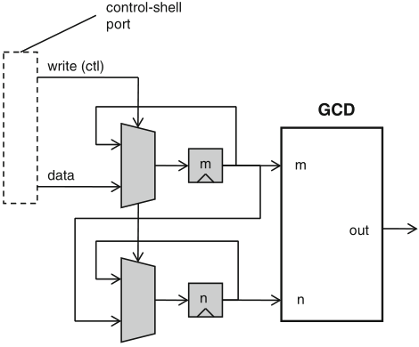
Schaumont, Figure 12.3 - Time-multiplexing of two hardware-module ports over a single control-shell port
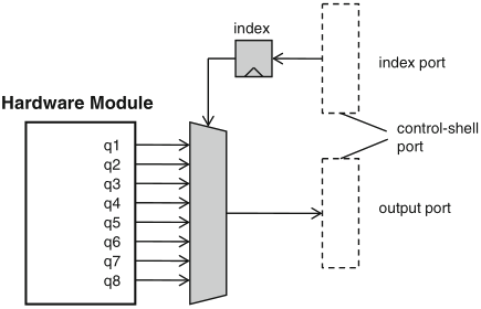
Schaumont, Figure 12.4 - Index-register to select one of eight output ports
multiplexing is also useful to handle long operands piecewise, whereby the operand can be provided one piece at a time by means of time-multiplexing
masking is a technique to work with very short operands, e.g. to group several single-bit ports of the hardware module in a hardware interface port: a mask register is used to this purpose, to bit-mask the module ports involved in an update, e.g.: new_hw_port = (old_hw_port & ~mask) | (upd_value & mask)
control design in a coprocessor is the collection of activities to generate control signals and to capture status signals
figure 12.5 shows a generic architecture to control a custom hardware module
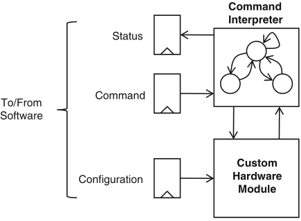
Schaumont, Figure 12.5 - Command design of a hardware interface
figure 12.6 shows the architecture of a coprocessor that can achieve communication/computation overlap, as illustrated in figure 12.7
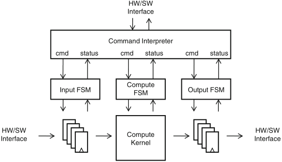
Schaumont, Figure 12.6 - Hierarchical control in a coprocessor
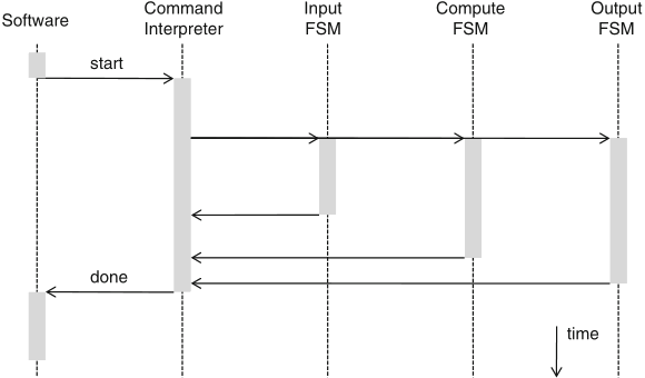
Schaumont, Figure 12.7 - Execution overlap using hierarchical control
the command interpreter analyzes each command from software and splits it up into a combination of commands for the lower-level FSMs
to effectively achieve execution overlap, a pipelining of the FSM actions is to be organized, where the command interpreter should adapt to the individual schedules of the lower-level FSMs