DMI – Graduate Course in Computer Science
Copyleft
![]() 2019 Giuseppe Scollo
2019 Giuseppe Scollo
![]()
hardware mapping of datapath expressions: same basic rules as with always blocks, however:
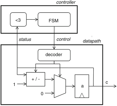
Schaumont, Figure 5.8 - Implementation of the up-down counter FSMD
the presented algorithm requires 192 I/O lines and 10 comparators
to this end the hardware stores the four data preceding the last one from the input stream and at every iteration with a new input element reuses the stored results of six comparisons from the previous three iterations
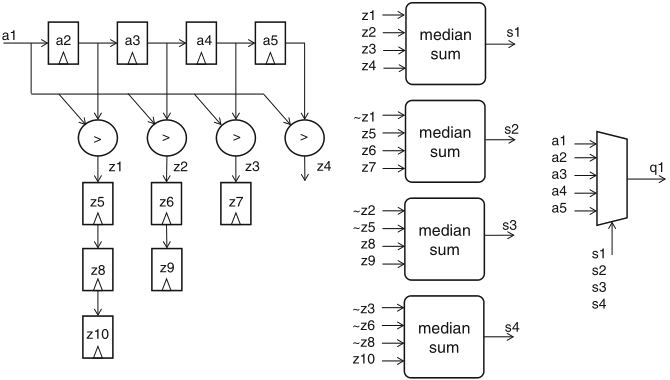
Schaumont, Figure 5.9 - Median-calculation datapath for a stream of values
dp median(in a1 : ns(32); out q1 : ns(32)) {
reg a2, a3, a4, a5 : ns(32);
sig z1, z2, z3, z4;
reg z5, z6, z7, z8, z9, z10 : ns(3);
sig s1, s2, s3, s4, s5 : ns(1);
always {
a2 = a1;
a3 = a2;
a4 = a3;
a5 = a4;
z1 = (a1 < a2);
z2 = (a1 < a3);
z3 = (a1 < a4);
z4 = (a1 < a5);
z5 = z1;
z6 = z2;
z7 = z3;
z8 = z5;
z9 = z6;
z10 = z8;
s1 =
(( z1 + z2 +
z3 + z4) == 2);
s2 =
(((1-z1) + z5 +
z6 + z7) == 2);
s3 =
(((1-z2) + (1-z5) +
z8 + z9) == 2);
s4 =
(((1-z3) + (1-z6) + (1-z8) + z10) == 2);
q1 =
s1 ? a1 : s2 ? a2 : s3 ? a3 : s4 ? a4 : a5;
}
}
the filter in fig 5.9 accepts a new input and produces a new output at every clock cycle
the figure shows the schedule, the FSMD which implements this idea is in Schaumont Sect. 5.5.4, which also presents the testbench FSMD here reproduced aside the figure
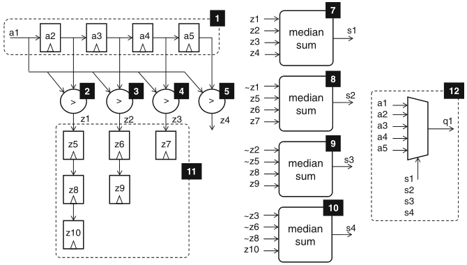
Schaumont, Figure 5.10 - Sequential schedule median-calculation datapath for a stream of values
dp t_median {
sig istr, ostr : ns(1);
sig a1_in, q1 : ns(32);
use median(istr, a1_in, ostr, q1);
reg r : ns(1);
reg c : ns(16);
always { r = ostr; }
sfg init { c = 0x1234; }
sfg sendin { a1_in = c;
c = (c[0] ˆ c[2] ˆ c[3] ˆ c[5]) # c[15:1];
istr = 1; }
sfg noin { a1_in = 0;
istr = 0; }
}
fsm ctl_t_median(t_median) {
initial s0;
state s1, s2;
@s0 (init, noin) -> s1;
@s1 (sendin) -> s2;
@s2 if (r) then (noin) -> s1;
else (noin) -> s2;
}
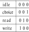
a simple example: memory controller
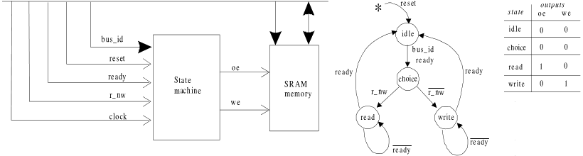
State transition diagram of a memory controller
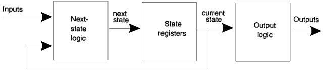
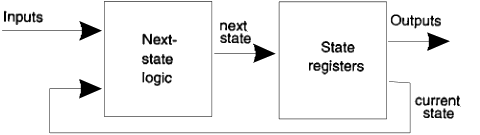
general FSM hardware structure
FSM hardware structure
in the VHDL description, states form an enumerated type
(see enclosed code):
Current-state dependent outputs (Moore FSM)
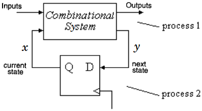
the block diagram corresponds to the two-process and one-process descriptions in the enclosed code
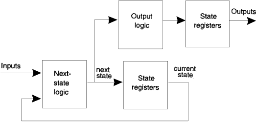
Next-state dependent outputs
this may be reduced to the flip-flop clock-to-q delay by computing outputs based on the next state and by placing registers before outputs
N.B. since processes are sequential, this optimization is also applicable to two-process and one-process architectures as well, by deferring outputs' updates until after state updates
Reduction of clock-output delay
another optimization technique consists in encoding states so as to let outputs coincide with some of the (encoded) state bits
e.g. in the seen example: