DMI – Graduate Course in Computer Science
Copyleft
![]() 2019 Giuseppe Scollo
2019 Giuseppe Scollo
outline:
FSM, a common control model for hardware description (and more):
a few variations:
FSM models are often presented as labelled transition graphs
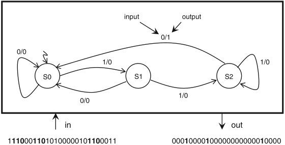
here is an example of Mealy FSM that recognizes a binary pattern

Schaumont, Figure 5.5 - Mealy FSM of a recognizer for the pattern ‘110’
the output '1' signals the recognition of an occurrence of the pattern in the binary input stream
it is possible to build an equivalent Moore FSM, by a general method
a simple procedure to convert a Mealy FSM into an equivalent Moore FSM:
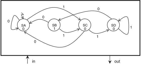
this procedure, together with the correspondence (s0,0) ↔ SA, (s0,1) ↔ SB, (s1,0) ↔ SC, (s2,0) ↔ SD, yields an equivalent Moore FSM for the recognizer of the pattern '110', presented in the figure:

Schaumont, Figure 5.6 - Moore FSM of a recognizer for the pattern ‘110’
the FSMD model combines dataflow processing with control over it, described by an FSM
to this purpose, instructions are defined in a datapath description, that are executed under FSM control
in Gezel, sfg (signal flow graph) blocks represent such instructions
an FSM controller is defined for a specific datapath:
the counter, here described in Gezel, is initialized to 0, then it alternates
dp updown(out c :ns(3)) {
reg a : ns(3);
always { c = a; }
sfg inc { a = a + 1; } // instruction inc
sfg dec { a = a - 1; } // instruction dec
sfg clr { a = 0; } // instruction clr
}
Schaumont, Listing 5.12 - Datapath for an up-down counter with three instructions
fsm ctl_updown(updown) {
initial s0;
state s1, s2;
@s0 (clr) -> s1;
@s1 if (a < 3) then (inc) -> s1;
else (dec) -> s2;
@s2 if (a > 0) then (dec) -> s2;
else (inc) -> s1;
}
Schaumont, Listing 5.13 - Controller for the up-down counter
the next table shows what happens at every clock cycle, for the first ten cycles
| FSM | DP | DP | ||
| Cycle | curr | instr | expr | a curr |
| /next | /next | |||
| 0 | s0/s1 | clr | a = 0 | 0/0 |
| 1 | s1/s1 | inc | a = a+1 | 0/1 |
| 2 | s1/s1 | inc | a = a+1 | 1/2 |
| 3 | s1/s1 | inc | a = a+1 | 2/3 |
| 4 | s1/s2 | dec | a = a-1 | 3/2 |
| 5 | s2/s2 | dec | a = a-1 | 2/1 |
| 6 | s2/s2 | dec | a = a-1 | 1/0 |
| 7 | s2/s1 | inc | a = a+1 | 0/1 |
| 8 | s1/s1 | inc | a = a+1 | 1/2 |
| 9 | s1/s1 | inc | a = a+1 | 2/3 |
Schaumont, Table 5.4 - Behavior of the FSMD in Listing 5.13
the algorithm is slightly different from that seen in the previous lab tutorial:
dp euclid(in m_in, n_in : ns(16);
out gcd : ns(16)) {
reg m, n : ns(16);
reg done : ns(1);
sfg init { m = m_in;
n = n_in;
done = 0;
gcd = 0; }
sfg reduce { m = (m >= n) ? m - n : m;
n = (n > m) ? n - m : n; }
sfg outidle { gcd = 0;
done = ((m == 0) | (n == 0)); }
sfg complete{ gcd = ((m > n) ? m : n);
$display(‘‘gcd = ’’, gcd); }
}
Schaumont, Listing 5.14 - Euclid’s GCD as an FSMD
fsm euclid_ctl(euclid) {
initial s0;
state s1, s2;
@s0 (init) -> s1;
@s1 if (done) then (complete) -> s2;
else (reduce, outidle) -> s1;
@s2 (outidle) -> s2;
}
control elements introduced with the FSM: almost all those proposed in the previous lab experience
N.B.: the execution of reduce and outidle fired by the FSM in state s1 is concurrent
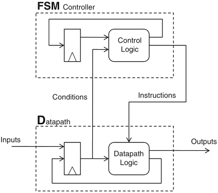
a dataflow model may be viewed as an FSM as well, with state space defined by its registers

Schaumont, Figure 5.7 - An FSMD consists of two stacked FSMs
FSM activities through each clock cycle:
in practice it is convenient to describe only the controller FSM by state transitions
if a datapath, which can be viewed as an FSM, may be described by expressions, this should be possible for the controller FSM as well
dp updown_ctl(in a_sm_3, a_gt_0 : ns(1);
out instruction : ns(2)) {
reg state_reg : ns(2);
// state encoding: s0 = 0, s1 = 1, s2 = 2
// instruction encoding: clr = 0, inc = 1, dec = 2
always {
state_reg = (state_reg == 0) ? 1 :
((state_reg == 1) & a_sm_3) ? 1 :
((state_reg == 1) & ˜a_sm_3) ? 2 :
((state_reg == 2) & a_gt_0) ? 2 : 1;
instruction = (state_reg == 0) ? 0 :
((state_reg == 1) & a_sm_3) ? 1 :
((state_reg == 1) & ˜a_sm_3) ? 2 :
((state_reg == 2) & a_gt_0) ? 2 : 1;
}
}
Schaumont, Listing 5.15 - FSM controller for updown counter using expressions
a comparison with the example description in Listing 5.13 shows:
on the other hand, separate descriptions of controller and datapath by expressions may be combined into a single description, whereby some performance enhancement may be gained
dp updown_ctl(out c : ns(3)) {
reg a : ns(3);
reg state : ns(2);
sig a_sm_3 : ns(1);
sig a_gt_0 : ns(1);
// state encoding: s0 = 0, s1 = 1, s2 = 2
always {
state = (state == 0) ? 1 :
((state == 1) & a_sm_3) ? 1 :
((state == 1) & ˜a_sm_3) ? 2 :
((state == 2) & a_gt_0) ? 2 : 1;
a_sm_3 = (a < 3);
a_gt_0 = (a > 0);
a = (state == 0) ? 0 :
((state == 1) & a_sm_3) ? a + 1 :
((state == 1) & ˜a_sm_3) ? a - 1 :
((state == 2) & a_gt_0) ? a + 1 : a - 1;
c = a;
}
}
Schaumont, Listing 5.16 - updown counter using expressions
the comparison of the two-part FSMD description given in Listings 5.12 and 5.13 with this monolithic description shows that in the latter:
on the other hand, single description offers more optimization opportunities:
for complex, highly structured applications, FSMD description with separate FSM and datapath descriptions seems to be preferable
a proper FSMD is one which has deterministic behaviour
for a hardware FSMD implementation, deterministic behaviour means that the hardware is race-free
an FSMD model is proper if it satisifies the following properties:
recommended readings:
for further consultation: