DMI – Graduate Course in Computer Science
Copyleft
![]() 2016-2017 Giuseppe Scollo
2016-2017 Giuseppe Scollo
![]()
here is an example of Mealy FSM that recognizes a binary pattern
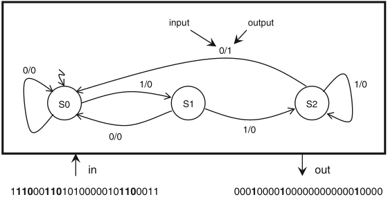
Schaumont, Figure 5.5 - Mealy FSM of a recognizer for the pattern ‘110’
the output '1' signals the recognition of an occurrence of the pattern in the binary input stream
it is possible to build an equivalent Moore FSM, by a general method
a simple procedure to convert a Mealy FSM into an equivalent Moore FSM:
this procedure, together with the correspondence (s0,0) ↔ SA, (s0,1) ↔ SB, (s1,0) ↔ SC, (s2,0) ↔ SD, yields an equivalent Moore FSM for the recognizer of the pattern '110', presented in the figure:
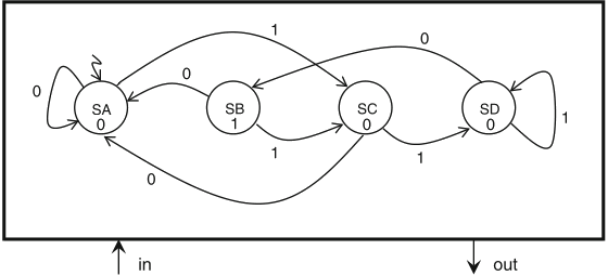
Schaumont, Figure 5.6 - Moore FSM of a recognizer for the pattern ‘110’
a dataflow model may be viewed as an FSM as well, with state space defined by its registers
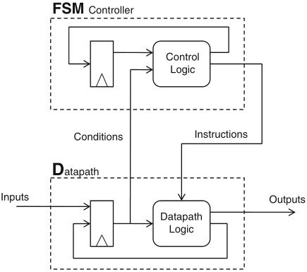
Schaumont, Figure 5.7 - An FSMD consists of two stacked FSMs
FSM activities through each clock cycle:
in practice it is convenient to describe only the controller FSM by state transitions