pencil and rubber

Logo of Triple-A Level WCAG-1 Conformance, W3C-WAI Web Content Accessibility Guidelines 1.0

XHTML 1.0 Conformance Validation CSS 3 Conformance Validation
Logo of Department of Mathematics and Computer Science, Course on Dedicated systems, link to Forum

On-chip bus systems, SoC development with FPGA

Tutorial 10 on Dedicated systems

Teacher: Giuseppe Scollo

University of Catania
Department of Mathematics and Computer Science
Graduate Course in Computer Science, 2016-17

Table of Contents

  1. On-chip bus systems, SoC development with FPGA
  2. tutorial outline
  3. on-chip bus standards
  4. bus components
  5. physical implementation of on-chip busses
  6. bus naming conventions
  7. bus timing diagrams
  8. a generic bus definition
  9. correspondence of standard busses to the generic bus
  10. lab experience
  11. references

tutorial outline

this tutorial deals with:

on-chip bus standards

four families of on-chip bus standards, among the most widely used ones:

two main classes of bus configurations: shared and point-to-point

a generic shared bus and a point-to-point one are considered next, abstracting common features of all of them


Bus
High-performance
shared bus
Periferal
shared bus
Point-to-point
bus

AMBA v3 AHB APB  
AMBA v4 AXI4 AXI4-lite AXI4-stream
CoreConnect PLB OPB  
Wishbone Crossbar topology Shared topology Point to point topology
Avalon Avalon-MM Avalon-MM Avalon-ST

AHB AMBA highspeed bus, APB AMBA peripheral bus, AXI advanced extensible interface,
PLB processor local bus, OPB onchip peripheral bus, MM memory-mapped, ST streaming

Schaumont, Table 10.1 - Bus configurations for existing bus standards

bus components

a shared bus on-chip typically consists of a few segments, connected by bridges; every transaction is initiated by a bus master, to which a slave responds; if they are on different segments, then the bridge acts as a slave on one side and as a master on the other side, while performing address translation

four classes of bus signals:

  • data : separate data lines for read and write
  • address : decoding may be centralized or local by the slaves
  • command : to distinguish read from write, often qualified by more signals
  • synchronization : clocks, distinct per bus segment, and possibly others, such as: handshake signals, time-out, etc.

Schaumont, Figura 10.1 - (a) esempio di sistmea di bus multi-master
          segmentato. (b) spazio di indirizzamento per lo stesso bus

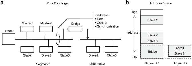
Schaumont, Figure 10.1 - (a) Example of a multi-master segmented bus system.
(b) Address space for the same bus

Schaumont, Figura 10.2 - bus punto-punto

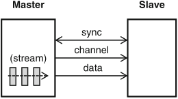
Schaumont, Figure 10.2 - Point-to-point bus

a point-to-point bus is a dedicated physical connection between a master and a slave, for unlimited stream data transfer

  • no address lines, but there may be for logical channel, in case of multiplexing of several streams over the same physical bus
  • synchronization very similar to the handshake protocol previously seen

physical implementation of on-chip busses

figure 10.3 shows the physical layout of a typical on-chip bus segment with two masters and two slaves, where AND and OR gates in the center of the diagram serve as multiplexers, of both address and data lines

Schaumont, Figura 10.3 - it: didascalia / en: caption text

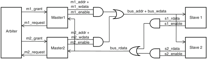
Schaumont, Figure 10.3 - Physical interconnection of a bus. The *_addr, *_wdata, *_sdata signals are signal vectors. The *_enable, *_grant, *_request signals are single-bit signals

signal naming convention about read/write data:

bus arbitration ensures that only one component may drive any given bus line at any time

bus naming conventions

naming conventions help one to infer the functionality and connectivity of wires based on their names

a component pin name will reflect the functionality of that pin; bus signals, which are created by interconnecting component pins, follow a convention, too, in order to avoid confusion between similar signals

in some bus systems, the instance names of both master and slave will be included as part of the bus signal name

adoption of the naming conventions of the particular bus in use avoids coding mistakes and connection errors, it makes code reusable, and it simplifies debugging and verification

bus timing diagrams

because of the inherently parallel nature of a bus system, timing diagrams are extensively used to describe the timing relationships of bus signals

Schaumont, Figura 10.4 - notazione dei diagrammi di temporizzazione
          nei bus

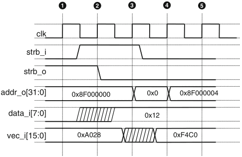
Schaumont, Figure 10.4 - Bus timing diagram notation

the diagram in figure 10.4 shows the notation to describe the activities in a generic bus over five clock cycles

  • all signals are referenced to the upgoing edge of the clock signal, shown on top
  • input signals in a clock cycle take their value before its starting clock edge
  • output signals established in a clock cycle take their value after its ending clock edge

bus timing diagrams are very useful to describe the activities on a bus as a function of time

a generic bus definition

table 10.2 lists the signals that make up a generic bus, abstracting from any specific bus system


Signal name Meaning

clk Clock signal. All other bus signals are references to the upgoing clock edge
m_addr Master address bus
m_data Data bus from master to slave (write operation)
s_data Data bus from slave to master (read operation)
m_rnw Read-not-Write. Control line to distinguish read from write operations
m_sel Master select signal, indicates that this master takes control of the bus
s_ack Slave acknowledge signal, indicates transfer completion
m_addr_valid Used in place of m_sel in split-transfers
s_addr_ack Used for the address in place of s_ack in split-transfers
s_wr_ack Used for the write-data in place of s_ack in split-transfers
s_rd_ack Used for the read-data in place of s_ack in split-transfers
m_burst Indicates the burst type of the current transfer
m_lock Indicates that the bus is locked for the current transfer
m_req Requests bus access to the bus arbiter
m_grant Indicates bus access is granted

Schaumont, Table 10.2 - Signals on the generic bus

correspondence of standard busses to the generic bus

table 10.3 shows the correspondence of some of the generic bus signals to equivalent signals of the CoreConnect/OPB, AMBA/APB, Avalon-MM, and Wishbone busses


generic CoreConnect/OPB AMBA/APB Avalon-MM Wishbone

clk OPB_CLK PCLK clk CLK_I (master/slave)
m_addr Mn_ABUS PADDR Mn_address ADDR_O (master)
        ADDR_I (slave)
m_rnw Mn_RNW PWRITE Mn_write_n WE_O (master)
m_sel Mn_Select PSEL   STB_O (master)
m_data OPB_DBUS PWDATA Mn_writedata DAT_O (master)
        DAT_I (slave)
s_data OPB_DBUS PRDATA Mb_readdata DAT_I (master)
        DAT_O (slave)
s_ack Sl_XferAck PREADY Sl_waitrequest ACK_O (slave)

Schaumont, Table 10.3 - Bus signals for simple read/write on Coreconnect/OPB, ARM/APB, Avalon-MM and Wishbone busses

lab experience

the two tutorials on the Qsys tool, available in Quartus, that are indicated in the references, respectively show how to:

it is proposed to replicate the execution of these two experiments and to expose, in the lab experience report, the encountered difficulties together with solutions adopted to overcome them

references

recommended readings:

readings for further consultation:

useful materials for the proposed lab experience: