DMI – Graduate Course in Computer Science
Copyleft
![]() 2016-2017 Giuseppe Scollo
2016-2017 Giuseppe Scollo
![]()
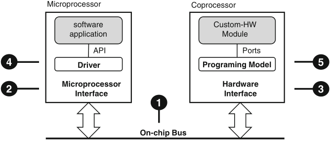
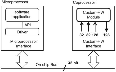
Schaumont, Figure 9.1 - The hardware/software interface
Figure 9.1 presents a synopsis of the elements in a hardware/software interface
the function of the hardware/software interface is to connect the software application to the custom-hardware module; this objective involves five elements:
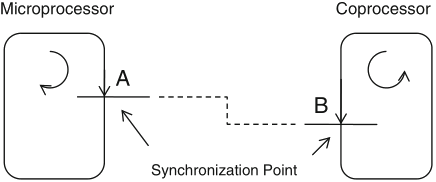
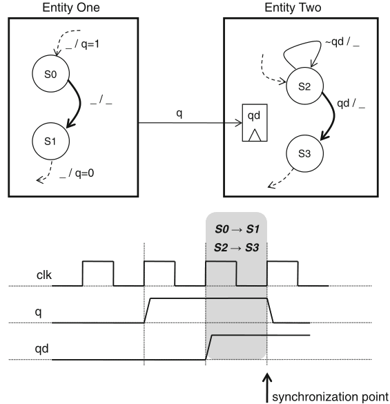
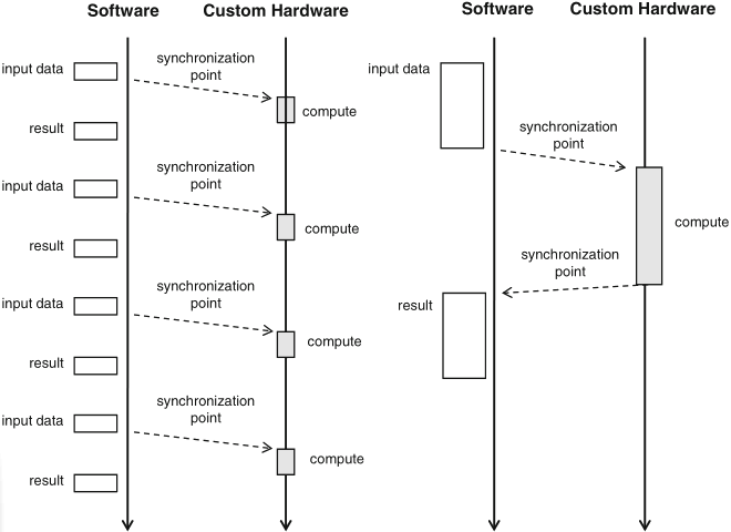
Schaumont, Figure 9.2 - Synchronization point
synchronization: the structured interaction of two otherwise independent and parallel entities
synchronization is needed to support communication between parallel subsystems: every talker needs to have a listener to be heard
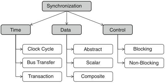
Schaumont, Figure 9.3 - Dimensions of the synchronization problem
three orthogonal dimensions of the synchronization problem:
semaphore: a synchronization primitive S to control access over an abstract, shared resource, by operations:
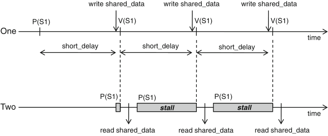
Schaumont, Figure 9.4 - Synchronization with a single semaphore
int shared_data;
semaphore S1;
entity one {
P(S1);
while (1) {
short_delay();
shared_data = ...;
V(S1);
// synchronization point
}
}
entity two {
short_delay();
while (1) {
P(S1);
// synchronization point
received_data = shared_data;
}
}
Schaumont, Listing 9.1 - One-way synchronization with a semaphore
synchronization points: when entity one calls V(S1), so unlocking the stalled entity two
just assume the opposite, viz. move the short_delay() function call from the while-loop in entity one to the while-loop in entity two ...
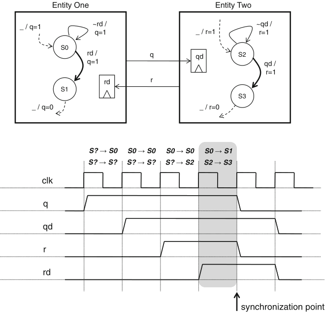
the situation of unknown delays can be addressed with a two-semaphore scheme
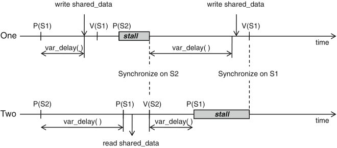
Schaumont, Figure 9.5 - Synchronization with two semaphores
int shared_data;
semaphore S1, S2;
entity one {
P(S1);
while (1) {
variable_delay();
shared_data = ...;
V(S1); // synchronization point 1
P(S2); // synchronization point 2
}
}
entity two {
P(S2);
while (1) {
variable_delay();
P(S1); // synchronization point 1
received_data = shared_data;
V(S2); // synchronization point 2
}
}
Schaumont, Listing 9.2 - Two-way synchronization with two semaphores
figure 9.5 illustrates the case where:
in parallel systems, a centralized semaphore may not be feasible; a common alternative is
computational speedup is often the motivation for the design of custom hardware
communication constraints need to be evaluated as well!
Schaumont, Figure 9.8 - Communication constraints of a coprocessor
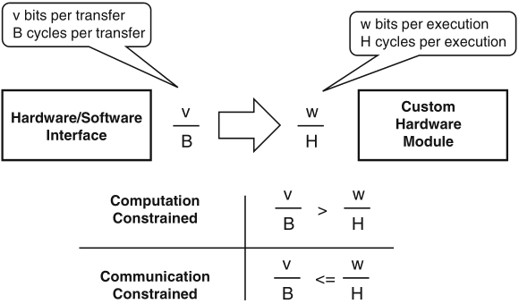
Schaumont, Figure 9.9 - Communication-constrained system vs. computation-constrained system
the number of clock cycles needed per execution of the custom hardware module is related to its hardware sharing factor (HSF) =def number of available clock cycles in between each I/O event
| Architecture | HSF |
| Systolic array processor | 1 |
| Bit-parallel processor | 1–10 |
| Bit-serial processor | 10–100 |
| Micro-coded processor | >100 |
Schaumont, Table 9.1 - Hardware sharing factor
coupling indicates the level of interaction between execution flows in software and custom hardware
coupling relates synchronization with performance
| Coprocessor | Memory-mapped | |
| Factor | interface | interface |
| Addressing | Processor-specific | On-chip bus address |
| Connection | Point-to-point | Shared |
| Latency | Fixed | Variable |
| Throughput | Higher | Lower |
Schaumont, Table 9.2 - Comparing a coprocessor interface with a memory-mapped interface
Schaumont, Figure 9.10 - Tight coupling versus loose coupling
example: difference between
N.B.: a high degree of parallelism in the overall design may be easier to achieve with a loosely-coupled scheme than with a tightly-coupled scheme