DMI – Graduate Course in Computer Science
Copyleft
![]() 2016-2017 Giuseppe Scollo
2016-2017 Giuseppe Scollo
![]()
problem: HW/SW partitioning the implementation of a dataflow system
here is a very simple example:
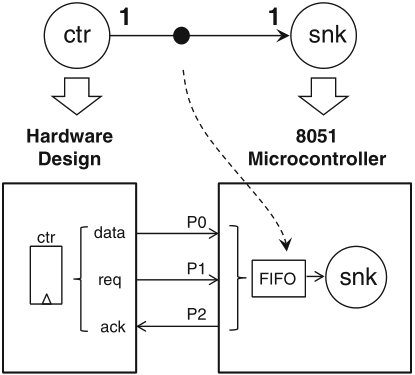
Schaumont, Figure 3.17 - Hybrid hardware/software implementation of a dataflow graph
hardware mapping of datapath expressions: same basic rules as with always blocks, however:
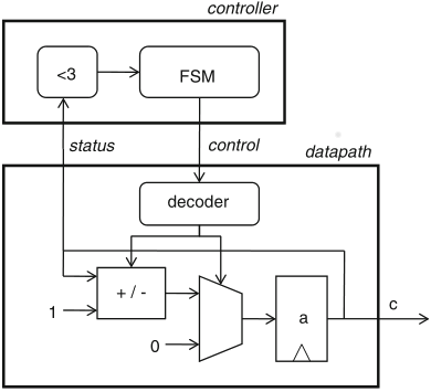
Schaumont, Figure 5.8 - Implementation of the up-down counter FSMD
the presented algorithm requires 192 I/O lines and 10 comparators
to this end the hardware stores the four data preceding the last one from the input stream and at every iteration with a new input element reuses the stored results of six comparisons from the previous three iterations
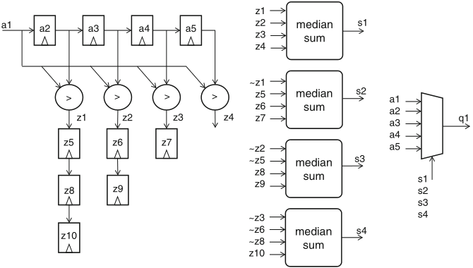
Schaumont, Figure 5.9 - Median-calculation datapath for a stream of values
dp median(in a1 : ns(32); out q1 : ns(32)) {
reg a2, a3, a4, a5 : ns(32);
sig z1, z2, z3, z4;
reg z5, z6, z7, z8, z9, z10 : ns(3);
sig s1, s2, s3, s4, s5 : ns(1);
always {
a2 = a1;
a3 = a2;
a4 = a3;
a5 = a4;
z1 = (a1 < a2);
z2 = (a1 < a3);
z3 = (a1 < a4);
z4 = (a1 < a5);
z5 = z1;
z6 = z2;
z7 = z3;
z8 = z5;
z9 = z6;
z10 = z8;
s1 =
(( z1 + z2 +
z3 + z4) == 2);
s2 =
(((1-z1) + z5 +
z6 + z7) == 2);
s3 =
(((1-z2) + (1-z5) +
z8 + z9) == 2);
s4 =
(((1-z3) + (1-z6) + (1-z8) + z10) == 2);
q1 =
s1 ? a1 : s2 ? a2 : s3 ? a3 : s4 ? a4 : a5;
}
}
the filter in fig 5.9 accepts a new input and produces a new output at every clock cycle
the figure shows the schedule, the FSMD which implements this idea is in Schaumont Sect. 5.5.4, which also presents the testbench FSMD here reproduced aside the figure
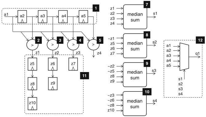
Schaumont, Figure 5.10 - Sequential schedule median-calculation datapath for a stream of values
dp t_median {
sig istr, ostr : ns(1);
sig a1_in, q1 : ns(32);
use median(istr, a1_in, ostr, q1);
reg r : ns(1);
reg c : ns(16);
always { r = ostr; }
sfg init { c = 0x1234; }
sfg sendin { a1_in = c;
c = (c[0] ˆ c[2] ˆ c[3] ˆ c[5]) # c[15:1];
istr = 1; }
sfg noin { a1_in = 0;
istr = 0; }
}
fsm ctl_t_median(t_median) {
initial s0;
state s1, s2;
@s0 (init, noin) -> s1;
@s1 (sendin) -> s2;
@s2 if (r) then (noin) -> s1;
else (noin) -> s2;
}
general hardware structure of an FSM and example of VHDL description of a Moore FSM:
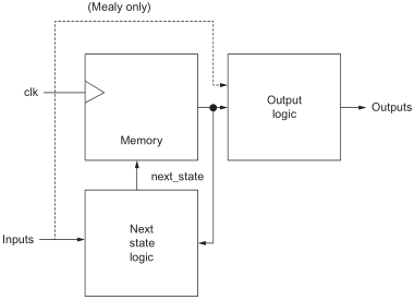
Wilson, Figure 22.1 - Hardware state machine structure
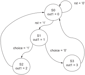
Wilson, Figure 22.2 - State transition diagram
the VHDL description of the example is taken from the textbook by Wilson, with several amendments
what about the sensitivity list of the second process? the author refers to an implicit clock... the simulation agrees with this, yet the compilation issues a warning in this respect
library ieee;
use ieee.std_logic_1164.all;
entity fsm is
port(
clk, rst, choice : in std_logic;
out1 : out std_logic_vector(1 downto 0)
);
end entity fsm;
architecture simple of fsm is
type state_type is ( s0, s1, s2, s3 );
signal current, next_state : state_type;
begin
process ( clk )
begin
if ( clk = '1' ) then
current <= next_state;
end if;
end process;
process ( current )
begin
case current is
when s0 =>
out1 <= "00";
if ( rst = '1') then
next_state <= s1;
else
next_state <= s0;
end if;
when s1=>
out1 <= "01";
if ( choice = '0') then
next_state <= s3;
else
next_state <= s2;
end if;
when s2=>
out1 <= "10";
next_state <= s0;
when s3=>
out1 <= "11";
next_state <= s0;
end case;
end process;
end;