DMI – Graduate Course in Computer Science
Copyleft
![]() 2016-2017 Giuseppe Scollo
2016-2017 Giuseppe Scollo
![]()
algorithm: at each step (a, b) is replaced by (|a-b|, min(a,b))
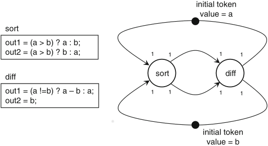
Schaumont, Figure 3.10 - Euclid’s greatest common divisor as an SDF graph
PASS analysis:
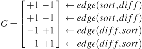
rank(G) = 1
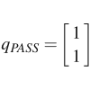
by the aforementioned three rules for a hardware implementation of the SDF model:
implementing the actors is a simple matter, by means of a few commonly used modules (multiplexers, comparators and a subtractor)
Schaumont, Figure 3.11 - Hardware implementation of Euclid’s algorithm
example of throughput enhancement by pipelining:
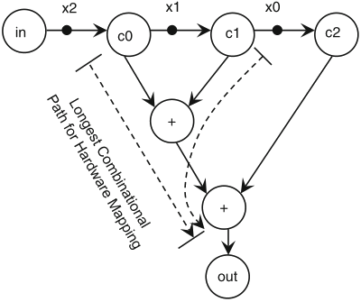
Schaumont, Figure 3.12 - SDF graph of a simple moving-average application
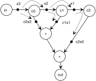
Schaumont, Figure 3.13 - Pipelining the moving-average filter by inserting additional tokens (1)
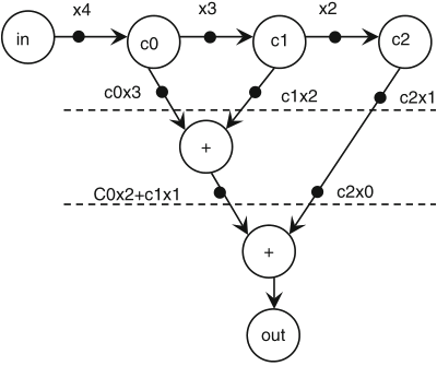
Schaumont, Figure 3.14 - Pipelining the moving-average filter by inserting additional tokens (2)
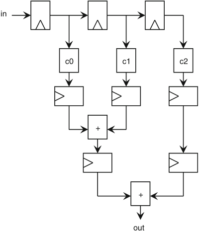
Schaumont, Figure 3.15 - Hardware implementation of the moving-average filter
remarks:
by introducing new tokens, pipelining may change the behaviour of an SDF graph
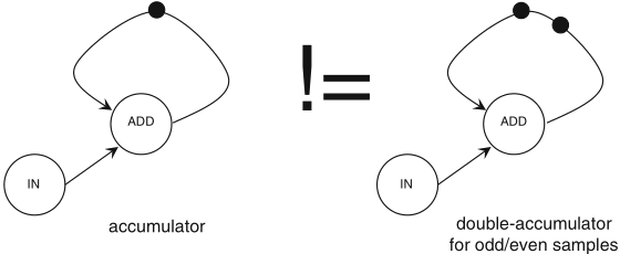
Schaumont, Figure 3.16 - Loops in SDF graphs cannot be pipelined
in order to apply pipelining without changing the functional behaviour of an SDF graph with cycles, the additional tokens should be placed outside of any loop in the graph