DMI – Graduate Course in Computer Science
Copyleft
![]() 2018 Giuseppe Scollo
2018 Giuseppe Scollo
![]()
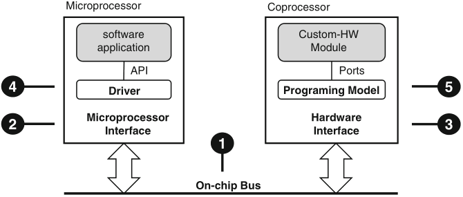
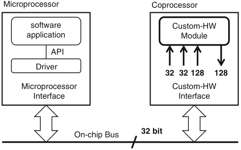
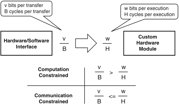
Schaumont, Figure 9.1 - The hardware/software interface
Figure 9.1 presents a synopsis of the elements in a HW/SW interface
the function of the HW/SW interface is to connect the software application to the custom-hardware module; this objective involves five elements:
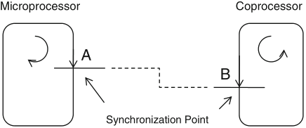
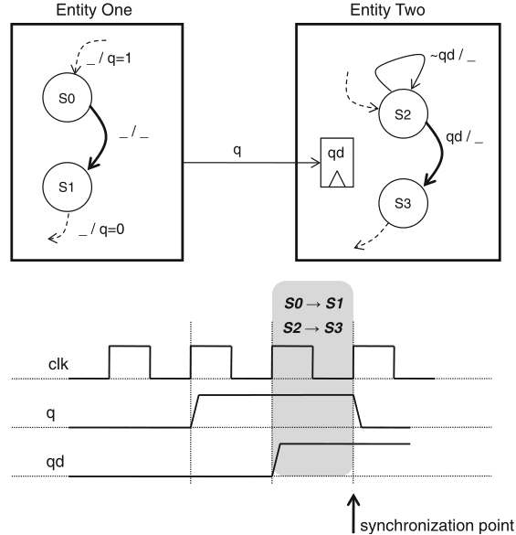
Schaumont, Figure 9.2 - Synchronization point
synchronization: the structured interaction of two otherwise independent and parallel entities
synchronization is needed to support communication between parallel subsystems: every talker needs to have a listener to be heard
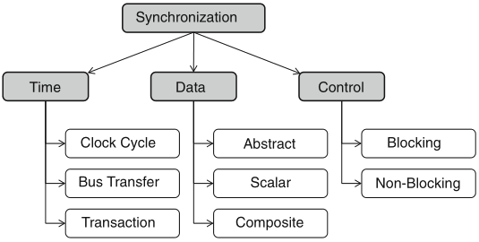
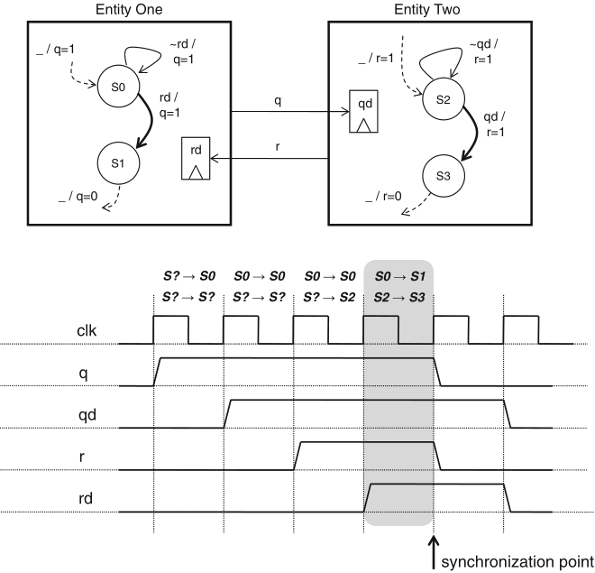
Schaumont, Figure 9.3 - Dimensions of the synchronization problem
three orthogonal dimensions of the synchronization problem:
semaphore: a synchronization primitive S to control access over an abstract, shared resource, by operations:
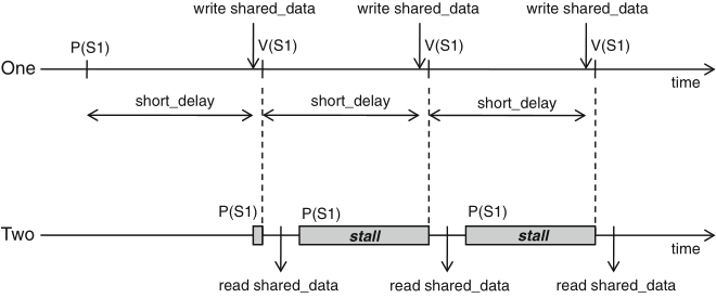
Schaumont, Figure 9.4 - Synchronization with a single semaphore
int shared_data;
semaphore S1;
entity one {
P(S1);
while (1) {
short_delay();
shared_data = ...;
V(S1);
// synchronization point
}
}
entity two {
short_delay();
while (1) {
P(S1);
// synchronization point
received_data = shared_data;
}
}
Schaumont, Listing 9.1 - One-way synchronization with a semaphore
synchronization points: when entity one calls V(S1), so unlocking the stalled entity two
just assume the opposite, viz. move the short_delay() function call from the while-loop in entity one to the while-loop in entity two ...
the situation of unknown delays can be addressed with a two-semaphore scheme
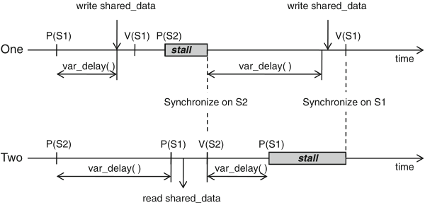
Schaumont, Figure 9.5 - Synchronization with two semaphores
int shared_data;
semaphore S1, S2;
entity one {
P(S1);
while (1) {
variable_delay();
shared_data = ...;
V(S1); // synchronization point 1
P(S2); // synchronization point 2
}
}
entity two {
P(S2);
while (1) {
variable_delay();
P(S1); // synchronization point 1
received_data = shared_data;
V(S2); // synchronization point 2
}
}
Schaumont, Listing 9.2 - Two-way synchronization with two semaphores
figure 9.5 illustrates the case where:
in parallel systems, a centralized semaphore may not be feasible; a common alternative is
computational speedup is often the motivation for the design of custom hardware
communication constraints need to be evaluated as well!
Schaumont, Figure 9.8 - Communication constraints of a coprocessor
Schaumont, Figure 9.9 - Communication-constrained system vs. computation-constrained system
the number of clock cycles needed per execution of the custom hardware module is related to its hardware sharing factor (HSF) =def number of available clock cycles in between each I/O event
| Architecture | HSF |
| Systolic array processor | 1 |
| Bit-parallel processor | 1–10 |
| Bit-serial processor | 10–100 |
| Micro-coded processor | >100 |
Schaumont, Table 9.1 - Hardware sharing factor
coupling indicates the level of interaction between execution flows in software and custom hardware
coupling relates synchronization with performance
| Coprocessor | Memory-mapped | |
| Factor | interface | interface |
| Addressing | Processor-specific | On-chip bus address |
| Connection | Point-to-point | Shared |
| Latency | Fixed | Variable |
| Throughput | Higher | Lower |
Schaumont, Table 9.2 - Comparing a coprocessor interface with a memory-mapped interface
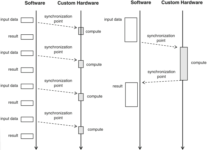
Schaumont, Figure 9.10 - Tight coupling versus loose coupling
example: difference between
N.B.: a high degree of parallelism in the overall design may be easier to achieve with a loosely-coupled scheme than with a tightly-coupled scheme
a shared bus on-chip typically consists of a few segments, connected by bridges; every transaction is initiated by a bus master, to which a slave responds; if they are on different segments, then the bridge acts as a slave on one side and as a master on the other side, while performing address translation
four classes of bus signals:
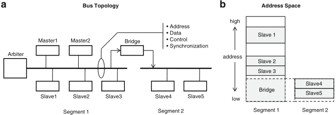
Schaumont, Figure 10.1
- (a) Example of a multi-master segmented bus system.
(b) Address space for the same bus
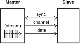
Schaumont, Figure 10.2 - Point-to-point bus
a point-to-point bus is a dedicated physical connection between a master and a slave, for unlimited stream data transfer
figure 10.3 shows the physical layout of a typical on-chip bus segment with two masters and two slaves, where AND and OR gates in the center of the diagram serve as multiplexers, of both address and data lines
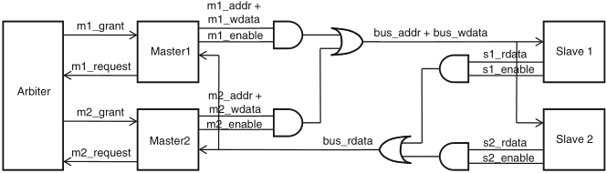
Schaumont, Figure 10.3 - Physical interconnection of a bus. The *_addr, *_wdata, *_sdata signals are signal vectors. The *_enable, *_grant, *_request signals are single-bit signals
signal naming convention about read/write data:
bus arbitration ensures that only one component may drive any given bus line at any time
naming conventions help one to infer functionality and connectivity of wires based on their names
a component pin name will reflect the functionality of that pin; bus signals, which are created by interconnecting component pins, follow a convention, too, in order to avoid confusion between similar signals
because of the inherently parallel nature of a bus system, timing diagrams are extensively used to describe the timing relationships of bus signals
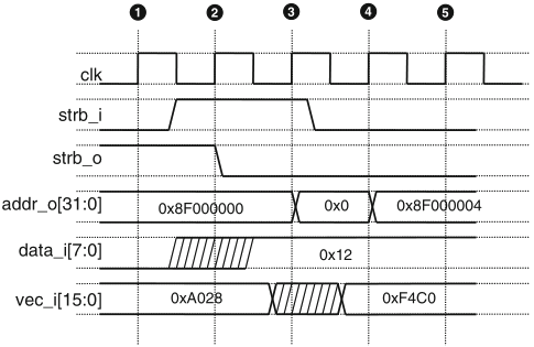
Schaumont, Figure 10.4 - Bus timing diagram notation
the diagram in figure 10.4 shows the notation to describe the activities in a generic bus over five clock cycles
bus timing diagrams are very useful to describe the activities on a bus as a function of time