DMI – Graduate Course in Computer Science
Copyleft
![]() 2018 Giuseppe Scollo
2018 Giuseppe Scollo
![]()
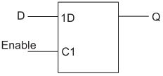
D latch symbol
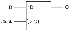
D type flip-flop
library ieee;
use ieee.std_logic_1164.all;
entity latch is
port (
d : in std_logic;
en : in std_logic;
q : out std_logic
);
end entity latch;
architecture beh of latch is
begin
process (d, en) is
begin
if (en = ’1’) then
q <= d;
end if;
end process;
end architecture beh;
library ieee;
use ieee.std_logic_1164.all;
entity dff is
port (
d : in std_logic;
clk : in std_logic;
q : out std_logic
);
end entity dff;
architecture simple of dff is
begin
process (clk) is
begin
if rising_edge(clk) then
q <= d;
end if;
end process;
end architecture simple;
library ieee;
use ieee.std_logic_1164.all;
entity register is
generic ( n : natural := 8 );
port (
d : in std_logic_vector(n−1 downto 1);
clk : in std_logic;
nrst : in std_logic;
load : in std_logic;
q : out std_logic_vector(n−1 downto 1)
);
end entity register;
architecture beh of register is
begin
process (clk, nrst) is
begin
if (nrst = ’0’) then
q <= (others => ’0’);
elsif (rising_edge(clk) and (load = 1)) then
q <= d;
end if;
end process;
end architecture beh;
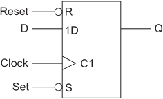
D-type flip-flop with asynchronous set and reset
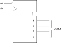
binary counter
the use of variables easies the VHDL description in behavioural style
library ieee;
use ieee.std_logic_1164.all;
use ieee.numeric_std.all;
entity counter is
generic ( n : integer := 4 );
port (
clk : in std_logic;
rst : in std_logic;
output : out std_logic_vector((n−1) downto 0)
);
end;
architecture simple of counter is
begin
process(clk, rst)
variable count : unsigned((n−1) downto 0);
begin
if rst = ’0’ then
count := (others => ’0’);
elsif rising_edge(clk) then
count := count + 1;
end if;
output <= std_logic_vector(count);
end process;
end;
library ieee;
use ieee.std_logic_1164.all;
entity shift_register is
generic ( n : integer := 4 );
port (
clk : in std_logic;
rst : in std_logic;
din : in std_logic;
q : out std_logic_vector((n−1) downto 0)
);
end entity;
architecture simple of shift_register is
begin
process(clk, rst)
variable shift_reg : std_logic_vector((n−1) downto 0);
begin
if rst = ’0’ then
shift_reg := (others => ’0’);
elsif rising_edge(clk) then
shift_reg := shift_reg(n−2 downto 0) & din;
end if;
q <= shift_reg;
end process;
end architecture simple;
algorithm: at each step (a, b) is replaced by (|a-b|, min(a,b))
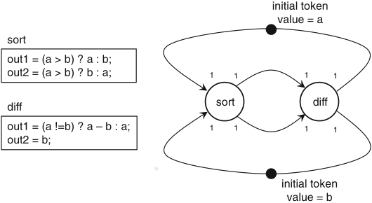
Schaumont, Figure 3.10 - Euclid’s greatest common divisor as an SDF graph
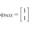
PASS analysis:
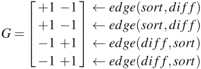
rank(G) = 1
by the aforementioned three rules for a hardware implementation of the SDF model:
implementing the actors is a simple matter, by means of a few commonly used modules (multiplexers, comparators and a subtractor)
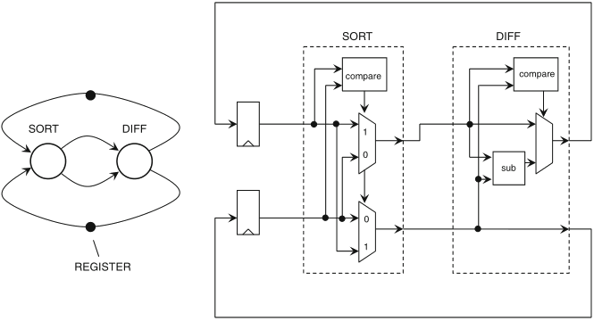
Schaumont, Figure 3.11 - Hardware implementation of Euclid’s algorithm
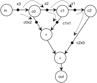
example of throughput enhancement by pipelining:
Schaumont, Figure 3.12
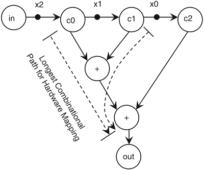
SDF graph of a simple moving-average application
Schaumont, Figure 3.13
Pipelining the moving-average filter by inserting additional tokens (1)
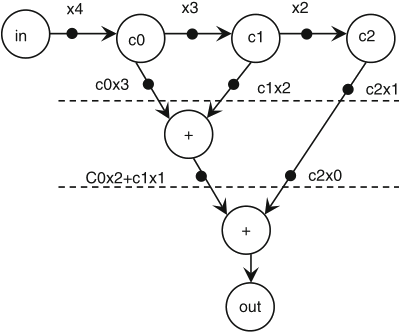
Schaumont, Figure 3.14
Pipelining the moving-average filter by inserting additional tokens (2)
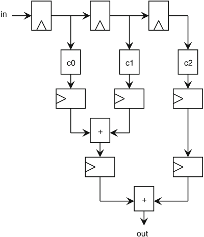
Schaumont, Figure 3.15
Hardware implementation of the moving-average filter
remarks:
by introducing new tokens, pipelining may change the behaviour of an SDF graph
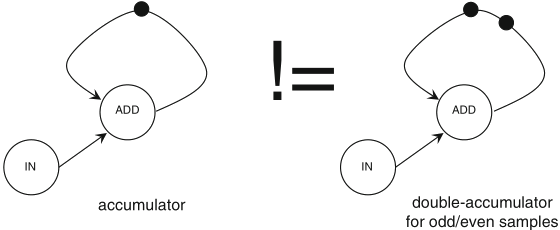
Schaumont, Figure 3.16 - Loops in SDF graphs cannot be pipelined
in order to apply pipelining without changing the functional behaviour of an SDF graph with cycles, the additional tokens should be placed outside of any loop in the graph