DMI – Graduate Course in Computer Science
Copyleft
![]() 2018 Giuseppe Scollo
2018 Giuseppe Scollo
![]()
the standard, two-valued boolean type BIT, does not suffice to represent all situations that may come into play in circuit design
tri-state gates are typically utilized to this purpose

tri-state buffer
the IEEE 1164 standard defines the nine-valued std_ulogic type:
yet std_ulogic does not allow multiple driver access to the same line
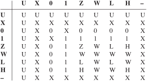
contention resolution between values of type std_logic
library ieee;
use ieee.std_logic_1164.all;
entity tri_state is
port (x, en : in std_logic;
y : out std_logic);
end entity tri_state;
architecture when_else of tri_state is
begin
y <= x when en = '1' else 'Z';
end architecture when_else;
functional unit that proves useful to diverse purposes, for example:
VHDL specification of the 2→4 decoder
library ieee;
use ieee.std_logic_1164.all;
entity decoder2 is
port (
a : in std_logic_vector(1 downto 0);
z : out std_logic_vector(3 downto 0)
);
end entity decoder2;
architecture when_else of decoder2 is
begin
z <= "0001" when a = "00" else
"0010" when a = "01" else
"0100" when a = "10" else
"1000" when a = "11" else
"XXXX";
end architecture when_else;
generic VHDL specification of the decoder (Zwolinski, sect. 4.2.3):
library ieee;
use ieee.std_logic_1164.all;
use ieee.numeric_std.all;
entity decoder is
generic (n : POSITIVE);
port (
a : in std_logic_vector(n-1 downto 0);
z : out std_logic_vector(2**n-1 downto 0)
);
end entity decoder;
architecture rotate of decoder is
constant z_out : BIT_VECTOR(2**n-1 downto 0) :=
(0 => '1', others => '0');
begin
z <= to_StdLogicVector (z_out sll
to_integer(unsigned(a)));
end architecture rotate;
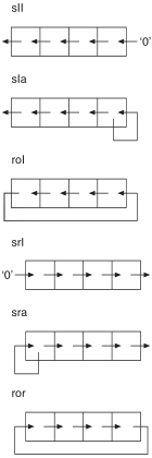
VHDL shift operators
familiar device of daily use ...
the following example (taken from Zwolinski, Sect. 4.2.3)
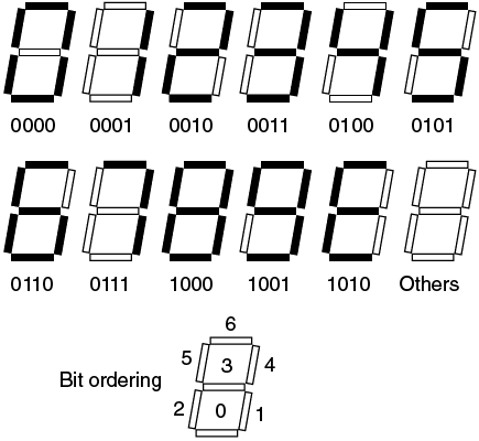
Zwolinski, Figure 4.3 - Seven-segment display
library ieee;
use ieee.std_logic_1164.all;
entity seven_seg is
port (a : in std_logic_vector(3 downto 0);
z : out std_logic_vector(6 downto 0));
end entity seven_seg;
architecture with_select of seven_seg is
begin
with a select
z <= "1110111" when "0000",
"0010010" when "0001",
"1011101" when "0010",
"1011011" when "0011",
"0111010" when "0100",
"1101011" when "0101",
"1101111" when "0110",
"1010010" when "0111",
"1111111" when "1000",
"1111011" when "1001",
"1101101" when
"1010"|"1011"|"1100"|"1101"|"1110"|"1111",
"0000000" when others;
end architecture with_select;
VHDL description of a multiplexer with a single select input:
library ieee;
use ieee.std_logic_1164.all;
entity mux1 is
port (
s : in std_logic;
a : in std_logic;
b : in std_logic;
y : out std_logic
);
end entity mux1;
architecture basic of mux1 is
begin
y <= a when s = ’0’ else
b when s = ’1’ else
’X’;
end architecture basic;
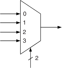
multiplexer with a 2-select input
how to generalize to n-select input?
description of an n-input OR gate:
library ieee;
use ieee.std_logic_1164.all;
entity wide_or is
generic (n : POSITIVE);
port (
x : in std_logic_vector(n-1 downto 0);
y : out std_logic);
end entity wide_or;
architecture sequential of wide_or is
begin
process (x) is
variable z : std_logic;
begin
z := x(0);
if n > 1 then
for i in 1 to n-1 loop
z := x(i) or z;
end loop;
end if;
y <= z;
end process;
end architecture sequential;
n-select input multiplexer
library ieee;
use ieee.std_logic_1164.all;
entity mux is
generic (n : POSITIVE := 1);
port (
s : in std_logic_vector(n-1 downto 0);
a : in std_logic_vector(2**n-1 downto 0);
z : out std_logic);
end entity mux;
architecture structural of mux is
signal decout : std_logic_vector(2**n-1 downto 0);
signal andout : std_logic_vector(2**n-1 downto 0);
begin
di: entity WORK.decoder generic map (n)
port map (a => s, z => decout);
oi: entity WORK.wide_or generic map (2**n)
port map (x => andout, y => z);
andout <= a and decout;
end architecture structural;
instantiation of the generic multiplexer
library ieee;
use ieee.std_logic_1164.all;
entity mux2 is
port (
s : in std_logic_vector(1 downto 0);
a : in std_logic_vector(3 downto 0);
z : out std_logic);
end entity mux2;
architecture instance of mux2 is
di: entity WORK.mux generic map (2)
port map (s, a, z);
end architecture instance;
an ALU is a multifunction unit: a control input selects the operation to be executed
| S | function |
| 00 | Q <= A or B |
| 01 | Q <= A and B |
| 10 | Q <= not B |
| 11 | Q <= A xor B |
library ieee;
use ieee.std_logic_1164.all;
entity alu_logic is
generic ( n : POSITIVE := 16 );
port (
a : in std_logic_vector((n−1) downto 0);
b : in std_logic_vector((n−1) downto 0);
s : in std_logic_vector(1 downto 0);
q : out std_logic_vector((n−1) downto 0)
);
end entity alu_logic;
architecture with_select of alu_logic is
constant undefined : std_logic_vector(n-1 downto 0) :=
(others => 'X');
begin
with s select
q <= a or b when “00”,
a and b when “01”,
not b; when “10”,
a xor b when “11”,
undefined when others;
end architecture with_select;
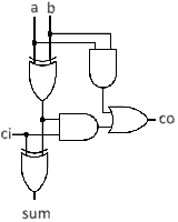
1-bit full-adder
for operands wider than one bit, ALU's arithmetic function may be specified in either structural or functional style; the latter as follows
library ieee;
use IEEE.std_logic_1164.all;
entity adder is
generic(n-1 : POSITIVE := 16);
port (
a : in std_logic_vector (n-1 downto 0);
b : in std_logic_vector (n-1 downto 0);
ci : in std_logic;
sum : out std_logic_vector (n-1 downto 0);
co : out std_logic
);
end entity adder;
architecture sequential of adder is
begin
process(a,b,ci)
variable carry : std_logic;
variable psum : std_logic_vector(n-1 downto 0);
begin
carry := ci;
for i in 0 to n-1 loop
psum(i) := a(i) xor b(i) xor carry;
carry :=
(a(i) and b(i)) or (((a(i) xor b(i)) and carry);
end loop;
sum <= psum;
co <= carry;
end process;
end architecture sequential;
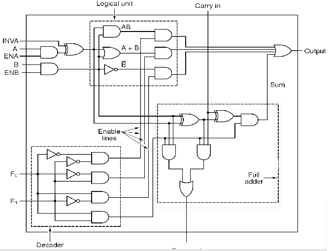
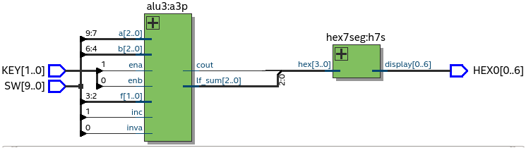
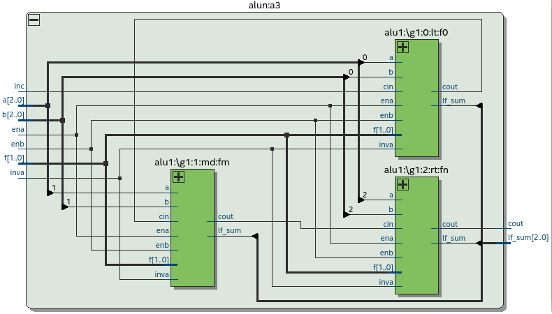
schematic of a 1-bit ALU (Figure 3-19 in (Tanenbaum, 2006))