pencil and rubber

Logo of Triple-A Level WCAG-1 Conformance, W3C-WAI Web Content Accessibility Guidelines 1.0

XHTML 1.0 Conformance Validation CSS 3 Conformance Validation
Logo of Department of Mathematics and Computer Science, Course on Dedicated systems, link to Forum

Program design and analysis for dedicated systems

Lecture 07 on Dedicated systems

Teacher: Giuseppe Scollo

University of Catania
Department of Mathematics and Computer Science
Graduate Course in Computer Science, 2016-17

Table of Contents

  1. Program design and analysis for dedicated systems
  2. lecture topics
  3. microprocessors, toolchain
  4. from C to (ARM) assembly: an example
  5. object code analysis
  6. data type representation
  7. variables in the memory hierarchy
  8. function calls: an example
  9. stack frame construction
  10. program layout in memory
  11. references

lecture topics

outline:

microprocessors, toolchain

microprocessor: most successful programmable component over the past decades... why?

  • separation of software from hardware through definition of an instruction set
  • wide availability of software tools to support program development, also in high-level languages
  • highly efficient options of reuse of components and of interoperability with other components, both hardware (standard bus) and software (libraries)
  • high scalability, e.g. 4-bit up to 64-bit word length, use of a microprocessor as coordination component in a complex SoC architecture, etc.

Schaumont, Figure 7.1 - standard design flow of software  
          source code to processor instruction

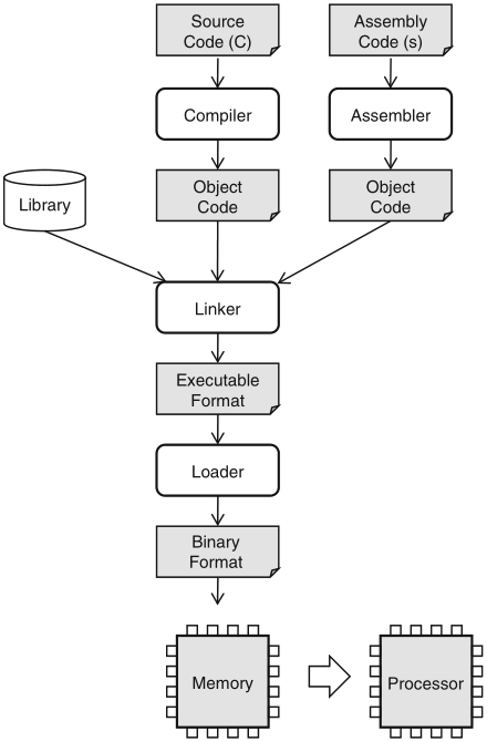
Schaumont, Figure 7.1 - Standard design flow of software source code to processor instruction

from C to (ARM) assembly: an example

int gcd(int a[5], int b[5]) {
  int i, m, n, max;
  max = 0;
  for (i=0; i<5; i++) {
    m = a[i];
    n = b[i];
    while (m != n) {
      if (m > n) m = m - n;
      else n = n - m;
    }
    if (max < m) max = m;
  }
  return max;
}
int a[] = {26, 3,33,56,11};
int b[] = {87,12,23,45,17};
int main() {
  return gcd(a, b);
}

Schaumont, Listing 7.1 - A C program to find a maximum GCD

Schaumont, Figure 7.2 - elements of an assembly program produced
          by gcc

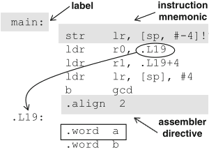
Schaumont, Figure 7.2 - Elements of an assembly program produced by gcc

gcd:    
  str lr, [sp, #-4]!
  mov lr, #0
  mov ip, lr
.L13:    
  ldr r3, [r0, ip, asl #2]
  ldr r2, [r1, ip, asl #2]
  cmp r3, r2
  beq .L17
.L11:    
  cmp r3, r2
  rsbgt r3, r2, r3
  rsble r2, r3, r2
  cmp r3, r2
  bne .L11
.L17:    
  add ip, ip, #1
  cmp lr, r3
  movlt lr, r3
  cmp ip, #4
  movgt r0, lr
  ldrgt pc, [sp], #4
  b .L13
a:    
  .word 26, 3, 33, 56, 11
b:    
  .word 87, 12, 23, 45, 17
main:    
  str lr, [sp, #-4]!
  ldr r0, .L19
  ldr r1, .L19+4
  ldr lr, [sp], #4
  b gcd
  .align 2
.L19:    
  .word a
  .word b

Schaumont, Listing 7.2 - ARM assembly dump of Listing 7.1

object code analysis

the symbolic assembly code of the example just seen, is obtained from the C source by running the command:

the command to generate the ARM ELF executable is:

it is also possible to obtain the symbolic code from the ELF executable by means of a disassembler, in this example with the following command:

the disassembler output also shows the binary code of each symbolic instruction and the address value of each label

data type representation

efficient hardware/software codesign requires a simultaneous understanding of both system architecture and software

data type representation is a good starting point, compilers are aware of differences in:

  • memory size
  • low-level implementation of operations

table 7.1 shows how C maps to the native data types supported by 32-bit processors

C data type  

char 8-bit
short signed 16-bit
int signed 32-bit
long signed 32-bit
long long signed 64-bit

Schaumont, Table 7.1 - Compiler data types

Schaumont, Figura 7.7 (a) - alignment of data types

Schaumont, Figure 7.7 (a) - Alignment of data types

word-based memory organization requires alignment to word boundaries, to perform a word transfer by a single memory access

  • the compiler generates directives to this purpose

Schaumont, Figura 7.7 (b) - little-endian and big-endian 
          storage order

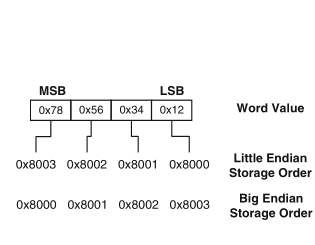
Schaumont, Figure 7.7 (b) - Little-endian and Big-endian storage order

byte ordering, in some cases even the bit-ordering, is relevant to hardware/software codesign

  • in the transition of software to hardware and back

variables in the memory hierarchy

another relevant aspect of data representation is what kind of physical memory they are assigned to

Schaumont, Figure 7.8 - memory hierarchy

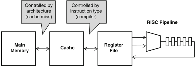
Schaumont, Figure 7.8 - Memory hierarchy

memory hierarchy is transparent to high-level programs, e.g. written in C, yet the low-level control affects performance; here is an example:

void accumulate(int *c, int a[10]) {
  int i;
  *c = 0;
  for (i=0; i<10; i++)
    *c += a[i];
}

/usr/local/arm/bin/arm-linux-gcc -O2 -c -S accumulate.c

generates the following code in accumulate.s :

  mov r3, #0  
  str r3, [r0, #0]  
  mov ip, r3  
.L6:      
  ldr r2, [r1, ip, asl #2] ; r2 ← a[i]
  ldr r3, [r0, #0] ; r3 ← *c (memory)
  add ip, ip, #1 ; increment loop ctr
  add r3, r3, r2  
  cmp ip, #9  
  str r3, [r0, #0] ; r3 → *c (memory)
  movgt pc, lr  
  b .L6  

in the example, the value of the accumulator variable travels up and down in the memory hierarchy

  • in C a limited control is available through use of storage class specifiers and type qualifiers
Storage specifier Type qualifier

register const
static volatile
extern  

function calls: an example

function calls are the fundamental structure of behavioural hierarchy of programs; here is an example of their translation to machine language

int accumulate(int a[10]) {
  int i;
  int c = 0;
  for (i=0; i<10; i++)
    c += a[i];
  return c;
}
int a[10];
int one = 1;
int main() {
  return one + accumulate(a);
}

Schaumont, Listing 7.4 - Sample program

compiling this program without optimization shows the creation of the activation frame within the stack, that is dynamically associated to the function execution to host local variables and register saving

  • in this case, the function parameter and return value are passed in register r0; when several parameters are to be passed, then the activation frame is made use of

the use of the frame pointer (FP) register enables call nesting and recursion

accumulate:    
  mov ip, sp  
  stmfd sp!, {fp, ip, lr, pc}  
  sub fp, ip, #4  
  sub sp, sp, #12  
  str r0, [fp, #-16] ; base address a
  mov r3, #0  
  str r3, [fp, #-24] ; c
  mov r3, #0  
  str r3, [fp, #-20] ; i
.L2:      
  ldr r3, [fp, #-20]  
  cmp r3, #9 ; i<10 ?
  ble .L5  
  b .L3  
.L5:      
  ldr r3, [fp, #-20] ; i * 4
  mov r2, r3, asl #2  
  ldr r3, [fp, #-16]  
  add r3, r2, r3 ; *a + 4 * i
  ldr r2, [fp, #-24]  
  ldr r3, [r3, #0]  
  add r3, r2, r3 ; c = c + a[i]
  str r3, [fp, #-24] ; update c
  ldr r3, [fp, #-20]  
  add r3, r3, #1  
  str r3, [fp, #-20] ; i = i + 1
  b .L2  
.L3:      
  ldr r3, [fp, #-24] ; return arg
  mov r0, r3  
  ldmea fp, {fp, sp, pc}  

Schaumont, Listing 7.6 - Accumulate without compiler optimizations

stack frame construction

figure 7.9 shows the construction of the activation frame in the stack

Schaumont, Figure 7.9 - stack frame construction

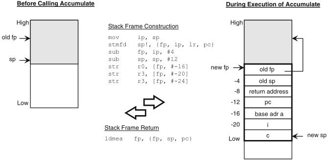
Schaumont, Figure 7.9 - Stack frame construction

the restoring of the saved registers and return take place by just one multiple transfer instruction

program layout in memory

for the physical representation of the program and its data structures in the memory hierarchy, a distinction is to be made between:

Schaumont, Figure 7.10 - static and dynamic program layout

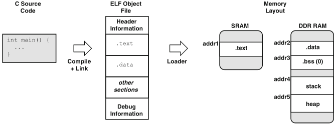
Schaumont, Figure 7.10 - Static and dynamic program layout

references

recommended readings:

for further consultation: