DMI – Graduate Course in Computer Science
Copyleft
![]() 2016-2017 Giuseppe Scollo
2016-2017 Giuseppe Scollo
![]()
starting from the eighties, RISC architectures (Reduced Instruction-Set Computer) have competed with CISC ones, to become dominant eventually
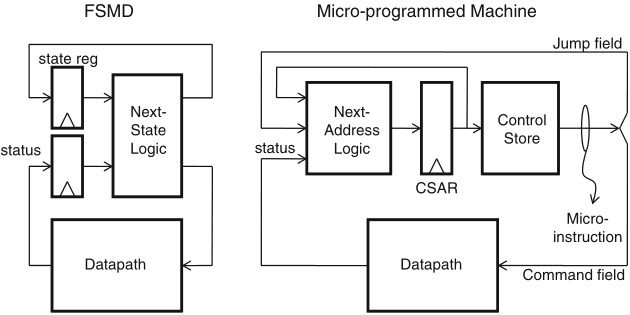
Schaumont, Figure 6.3 - In contrast to FSM-based control, microprogramming uses a flexible control scheme
CSAR (Control Store Address Register): analogue of the conventional Program Counter
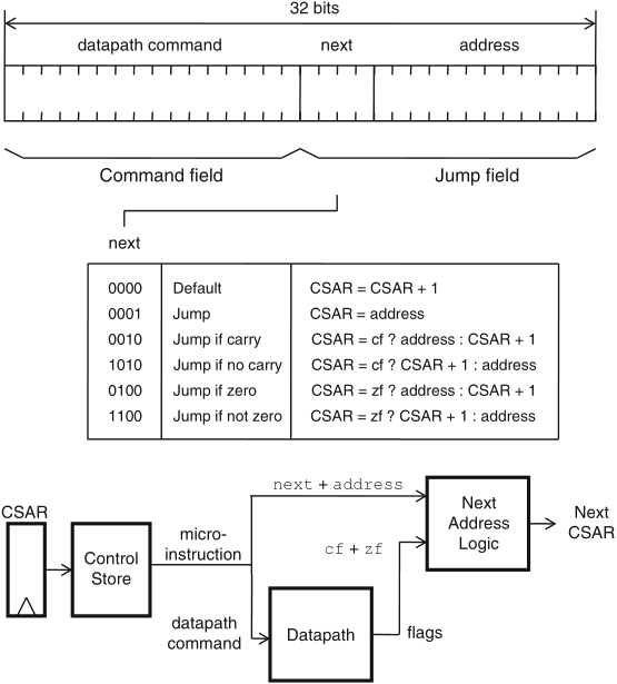
Schaumont, Figure 6.4 - Sample format for a 32-bit
micro-instruction word
microinstruction format and encoding is driven by design trade-offs; a sample encoding is as follows
the format in figure 6.4 is not optimal, as the address field is only used for jump instructions–it may be used for other purposes with other instructions
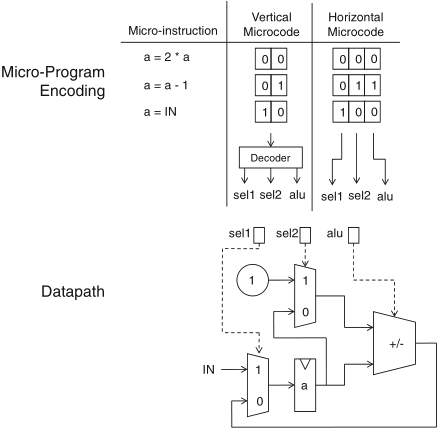
Schaumont, Figure 6.5 - Example of vertical versus horizontal
micro-programming
another space-time trade-off is presented by the alternative for the command field:
a combined solution is often adopted, e.g. the encoding in the next field:
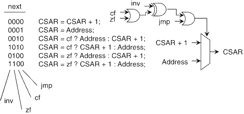
Schaumont, Figure 6.6 - CSAR encoding
here is an example of microprogrammed control of a datapath that includes: an ALU with shifter unit, a register file with eight entries, an accumulator register, and an input port
mixed horizontal/vertical encoding: overall horizontal, for each unit in the datapath takes a distinct portion of the control word, vertical encoding of each unit control signals in that portion
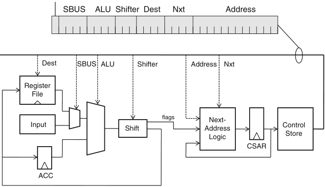
Schaumont, Figure 6.7 - A micro-programmed datapath
the shifter also generates flags, which are used by the microprogrammed controller to implement conditional jumps
control word fields:
the datapath fetches and executes a microinstruction every clock cycle
using the encoding defined in table 6.1, a microinstruction is formed by selecting a function for each module in the datapath and a next address for the Address field (with a suitable don't care value for this whenever Nxt is null)
by way of example, let's see how an RTL instruction, such as ACC ← R2, is translated to a microinstruction
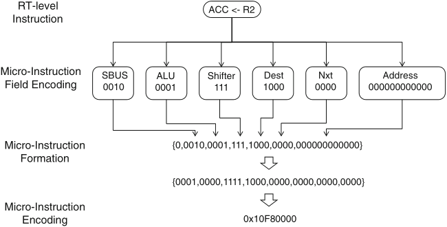
Schaumont, Figure 6.8 - Forming micro-instructions from register-transfer instructions