DMI – Graduate Course in Computer Science
Copyleft
![]() 2016-2017 Giuseppe Scollo
2016-2017 Giuseppe Scollo
![]()
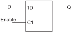
basic D latch symbol
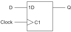
D type flip-flop
library ieee;
use ieee.std_logic_1164.all;
entity latch is
port (
d : in std_logic;
en : in std_logic;
q : out std_logic
);
end entity latch;
architecture beh of latch is
begin
process (d, en) is
begin
if (en = ’1’) then
q <= d;
end if;
end process;
end architecture beh;
library ieee;
use ieee.std_logic_1164.all;
entity dff is
port (
d : in std_logic;
clk : in std_logic;
q : out std_logic
);
end entity dff;
architecture simple of dff is
begin
process (clk) is
begin
if rising_edge(clk) then
q <= d;
end if;
end process;
end architecture simple;
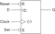
D-type flip-flop with asynchronous set and reset
exercise : correct the errors which affect the VHDL code presentated in the reference textbook, p. 290
library ieee;
use ieee.std_logic_1164.all;
entity register is
generic ( n : natural := 8 );
port (
d : in std_logic_vector(n−1 downto 1);
clk : in std_logic;
nrst : in std_logic;
load : in std_logic;
q : out std_logic_vector(n−1 downto 1)
);
end entity register;
architecture beh of register is
begin
process (clk, nrst) is
begin
if (nrst = ’0’) then
q <= (others => ’0’);
elsif (rising_edge(clk) and (load = 1)) then
q <= d;
end if;
end process;
end architecture beh;
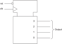
binary counter
the use of variables easies the VHDL description in behavioural style
library ieee;
use ieee.std_logic_1164.all;
use ieee.numeric_std.all;
entity counter is
generic ( n : integer := 4 );
port (
clk : in std_logic;
rst : in std_logic;
output : out std_logic_vector((n−1) downto 0)
);
end;
architecture simple of counter is
begin
process(clk, rst)
variable count : unsigned((n−1) downto 0);
begin
if rst = ’0’ then
count := (others => ’0’);
elsif rising_edge(clk) then
count := count + 1;
end if;
output <= std_logic_vector(count);
end process;
end;
library ieee;
use ieee.std_logic_1164.all;
entity shift_register is
generic ( n : integer := 4 );
port (
clk : in std_logic;
rst : in std_logic;
din : in std_logic;
q : out std_logic_vector((n−1) downto 0)
);
end entity;
architecture simple of shift_register is
begin
process(clk, rst)
variable shift_reg : std_logic_vector((n−1) downto 0);
begin
if rst = ’0’ then
shift_reg := (others => ’0’);
elsif rising_edge(clk) then
shift_reg := shift_reg(n−2 downto 0) & din;
end if;
q <= shift_reg;
end process;
end architecture simple;
an ALU is a multifunction unit: a control input selects the operation to be executed
| S | function |
| 00 | Q <= not A |
| 01 | Q <= A and B |
| 10 | Q <= A or B |
| 11 | Q <= A xor B |
library ieee;
use ieee.std_logic_1164.all;
entity alu_logic is
generic ( n : natural := 16 );
port (
a : in std_logic_vector((n−1) downto 0);
b : in std_logic_vector((n−1) downto 0);
s : in std_logic_vector(1 downto 0);
q : out std_logic_vector((n−1) downto 0)
);
end entity alu_logic;
architecture basic of alu_logic is
begin
case s is
when “00” => q <= not a;
when “01” => q <= a and b;
when “10” => q <= a or b;
when “11” => q <= a xor b;
end case;
end architecture basic;
arithmetic functions of the ALU may be specified in dataflow style or, for operands wider than one bit, in either structural or behavioural style; the latter as follows
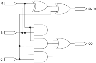
full-adder da 1 bit
library ieee;
use IEEE.std_logic_1164.all;
entity add_beh is
generic(top : natural := 15);
port (
a : in std_logic_vector (top downto 0);
b : in std_logic_vector (top downto 0);
cin : in std_logic;
sum : out std_logic_vector (top downto 0);
cout : out std_logic
);
end entity add_beh;
architecture behavior of add_beh is
begin
adder:
process(a,b,cin)
variable carry : std_logic;
variable tempsum : std_logic_vector(top downto 0);
begin
carry := cin;
for i in 0 to top loop
tempsum(i) := a(i) xor b(i) xor carry;
carry := (a(i) and b(i)) or (a(i) and carry) or (b(i) and carry);
end loop;
sum <= tempsum;
cout <= carry;
end process adder;
end architecture behavior;
probably the most used combinational functional units in digital hardware:
generic VHDL specification of the decoder (Zwolinski, sect. 4.2.3):
library ieee;
use ieee.std_logic_1164.all;
use ieee.numeric_std.all;
entity decoder is
generic (n : positive);
port (
a : in std_logic_vector(n-1 downto 0);
z : out std_logic_vector(2**n-1 downto 0)
);
end entity decoder;
architecture rotate of decoder is
constant z_out : bit_vector(2**n-1 downto 0) :=
(0 => '1', others => '0');
begin
z <= to_StdLogicVector (z_out sll
to_integer(unsigned(a)));
end architecture rotate;
VHDL description of a multiplexer with a single select line:
library ieee;
use ieee.std_logic_1164.all;
use ieee.numeric_std.all;
entity mux21 is
port (
s : in std_logic;
a : in std_logic;
b : in std_logic;
q : out std_logic
);
end;
architecture simple of mux21 is
begin
q <= a when s = ’0’ else
b when s = ’1’ else
’X’;
end;
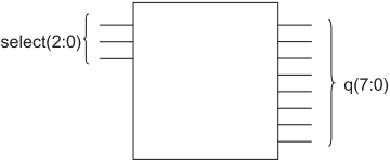
decoder 3-8
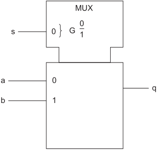
input multiplexer with a single select line
familiar device of daily use ...
the following example (taken from Zwolinski, Sect. 4.2.3)
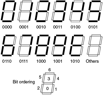
Zwolinski, Figure 4.3 - Seven-segment display
library ieee;
use ieee.std_logic_1164.all;
entity seven_seg is
port (a : in std_logic_vector(3 downto 0);
z : out std_logic_vector(6 downto 0));
end entity seven_seg;
architecture with_select of seven_seg is
begin
with a select
z <= "1110111" when "0000",
"0010010" when "0001",
"1011101" when "0010",
"1011011" when "0011",
"0111010" when "0100",
"1101011" when "0101",
"1101111" when "0110",
"1010010" when "0111",
"1111111" when "1000",
"1111011" when "1001",
"1101101" when
"1010"|"1011"|"1100"|"1101"|"1110"|"1111",
"0000000" when others;
end architecture with_select;